Magnetism and Electromagnetism Notes 9th Science Lesson 5 Notes in English
Magnetism and Electromagnetism Notes 9th Science Lesson 5 Notes in English
Introduction
- Have you ever played with magnets? Do you wonder why it attracts iron? Magnets are always attractive objects for the humans.
- In fact famous scientist Einstein has mentioned that he was always attracted by magnets in his childhood. In the olden days magnets were used in the ships.
- Captains of the ships effectively used the magnets to identify the direction of the ship in the sea.
- There are two kinds of magnets that we can see around us: Natural magnet and artificial magnet.
- Natural magnets exist in the nature. These kinds of magnets can be found in rocks and sandy deposits in various parts of the world.
- The strongest natural magnet is lodestone magnetite. The magnetic property in the natural magnets is permanent. It never gets destroyed.
- The lodestones were used to make compasses in the olden days. Artificial magnets are made by us.
- The magnets available in the shops are basically artificial magnets.
- In this lesson we shall study about properties of magnets, magnetic effect of current, electromagnetic induction and applications of electromagnets.
Magnetic field (B)
Activity 1
- Put a magnet on a table and place some paper clips nearby.
- If you push the magnet slowly towards the paper clips, there will be a point at which the paper clips jump across and stick to the magnet.
- What do you understand from this?
- From the above activity we notice that magnets have an invisible field all around them which attracts magnetic materials.
- In this space we can feel the force of attraction or repulsion due to the magnet.
- Thus, magnetic field is the region around the magnet where its magnetic influence can be felt.
- It is denoted by B and its unit is Tesla.
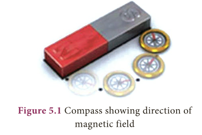
- The direction of the magnetic field around a magnet can be found by placing a small compass in the magnetic field (Fig 5.1).
- Magnetic field can penetrate through all kinds of materials, not just air.
- The Earth produces its own magnetic field, which shields the earth’s ozone layer from the solar wind and it is important for navigation also.
Magnetic Field Lines
- A magnetic field line is defined as a curve drawn in the magnetic field in such a way that the tangent to the curve at any point gives the direction of the magnetic field.
- They start at north pole and ends at south pole.
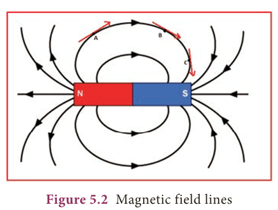
- In Figure 5.2, the arrow mark indicates the direction of magnetic field at points A, B and C.
- Note carefully that the magnetic field at a point is tangential to the magnetic field lines.
Magnetic flux
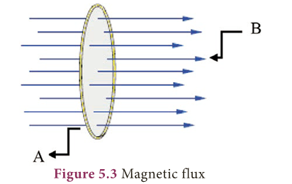
- Magnetic flux is the number of magnetic field lines passing through a given area (Fig. 5.3).
- It is denoted by ϕ and its unit is weber (Wb).
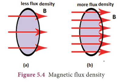
- The number of magnetic field lines crossing unit area kept normal to the direction of field lines is called magnetic flux density.
- It is shown in Figure 5.4.
- Its unit is Wb/m2
Properties of magnetic lines of force
- Magnetic lines of force are closed, continuous curves, extending through the body of the magnet.
- Magnetic lines of force start from the North Pole and end at the South Pole.
- Magnetic lines of force never intersect.
- They will be maximum at the poles than at the equator.
- The tangent drawn at any point on the curved line gives the direction of magnetic field.
Magnetic effect of current
- It was on 21st April 1820, Hans Christian Oersted, a Danish Physicist was giving a lecture.
- He was demonstrating electrical circuits in that class. He had to often switch on and off the circuit during the lecture.
- Accidentally, he noticed the needle of the magnetic compass that was on the table.
- It deflected whenever he switched on and the current was flowing through the wire.
- The compass needle moved only slightly, so that the audience didn’t even notice.
- But, it was clear to Oersted that something significant was happening.
- He conducted many experiments to find out a startling effect, the magnetic effect of current.
- Oersted aligned a wire XY such that they were exactly along the North-South direction.
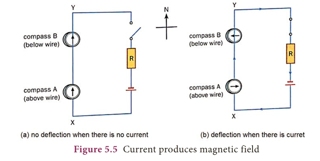
- He kept one magnetic compass above the wire at A and another under the wire at B.
- When the circuit was open and no current was flowing through it, the needle of both the compass was pointing to north.
- Once the circuit was closed and electric current was flowing, the needle at A pointed to east and the needle at B to the west as shown in Figure 5.5.
- This showed that current carrying conductor produces magnetic field around it.
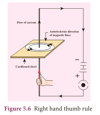
- The direction of the magnetic lines around a current carrying conductor can be easily understood using the right hand thumb rule.
- Hold the wire with four fingers of your right hand with thumbs-up position.
- If the direction of the current is towards the thumb then the magnetic lines curl in the same direction as your other four fingers as shown in Figure 5.6.
- This shows that the magnetic field is always perpendicular to the direction of current.
- The strength of the magnetic field at a point due to current carrying wire depends on:
- the current in the wire,
- distance of the point from the wire,
- the orientation of the point from the wire and
- the magnetic nature of the medium.
- The magnetic field lines are stronger near the current carrying wire and it diminishes as you go away from it.
- This is represented by drawing magnetic field lines closer together near the wire and farther away from the wire.
Force on a current carrying conductor in a magnetic field
- H.A.Lorentz found that a charge moving in a magnetic field, in a direction other than the direction of magnetic field, experiences a force. It is called the magnetic Lorentz force.
- Since charge in motion constitutes a current, a conductor carrying moving charges, placed in magnetic field other than the direction of magnetic field, will also experience a force and can produce motion in the conductor.
Activity 2
- Take a cardboard and thread a wire perpendicular through it.
- Connect the wire such that current flows up the wire. Switch on the circuit. Let the current flow.
- Place a magnetic compass on the cardboard and mark the position. Now move magnet and mark the new position.
- If you join all the points you will find that it is a circle.
- Reverse the direction of the current, you will find the magnetic circles are clockwise.
- From this activity, we infer that current carrying wire has a magnetic field perpendicular to the wire (by looking at the deflection of the compass needle in the vicinity of a current carrying conductor).
- The deflection of the needle implies that the current carrying conductor exerts a force on the compass needle.
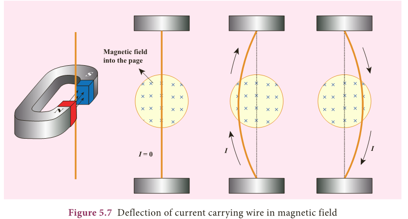
- In 1821, Michael Faraday discovered that a current carrying conductor also gets deflected when it is placed in a magnetic field.
- In Figure 5.7, we can see that the magnetic field of the permanent magnet and the magnetic field produced by the current carrying conductor interact and produce a force on the conductor.
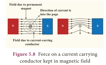
- The view perpendicular to the direction of current is shown in Figure 5.8.
- If a current, I is flowing through a conductor of length, L kept perpendicular to the magnetic field B, then the force F experienced by it is given by the equation,
- F = I L B
- The above equation indicates that the force is proportional to current through the conductor, length of the conductor and the magnetic field in which the current carrying conductor is kept.
- Note: The angle of inclination between the current and magnetic field also affects the magnetic force.
- When the conductor is perpendicular to the magnetic field, the force will be maximum (=BIL).
- When it is parallel to the magnetic field, the force will be zero. The force is always a vector quantity.
- A vector quantity has both magnitude and direction. It means we should know the direction in which the force would act.
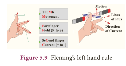
- The direction is often found using what is known as Fleming’s Left hand Rule (formulated by the scientist John Ambrose Fleming).
- The law states that while stretching the three fingers of left hand in perpendicular manner with each other, if the direction of the current is denoted by the middle finger of the left hand and the second finger is for direction of the magnetic field, then the thumb of the left hand denotes the direction of the force or movement of the conductor (Fig. 5.9)


Force on parallel current carrying conductors
- We have seen that a current carrying conductor has a magnetic field around it.
- If we place another conductor carrying current parallel to the first one, the second conductor will experience a force due to the magnetic field of the first conductor.
- Similarly, the first conductor will experience a force due to the magnetic field of the second conductor.
- These two forces will be equal in magnitude and opposite in direction.
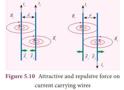
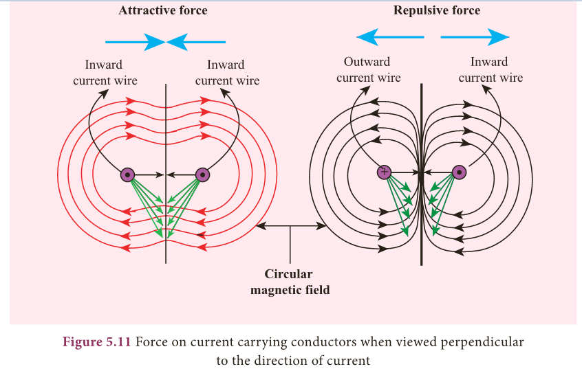
- Using Fleming’s left hand rule we can find that the direction of the force on each wire would be towards each other when the current in both of them are flowing in the same direction, i.e., the wires would experience an attractive force.
- However, if the direction of the flow of current is in opposite direction, then the force on each of the wire will be in opposite direction.
- These are shown in Figure 5.10 and the perpendicular view of the same is shown in Figure 5.11.
Connection between Electricity and Magnetism:
- Before 18th century people thought that magnetism and electricity were separate subjects of study.
- After Oersted’s experiment the electricity and magnetism were united and became a single subject called ‘Electromagnetism’.
- When there is current, the magnetic field is produced and the current carrying conductor behaves like a magnet.
- You may now wonder how was it possible for a lodestone to behave like a magnet when there was no current passing through it.
- Only in the twentieth century, we understood that the magnetic property arises due to the motion of electrons in the lodestone.
- In the circuit the electrons flow from negative of the battery to positive of the battery and constitutes current.
- As a result it produces magnetic field.
- In natural magnets and artificial magnets that we buy in shops, the electrons move around the nucleus constitutes current which leads to magnetic property.
- Here, every orbiting electron in its orbit is like a current carrying loop.
- Even though in all the materials electrons orbit around the nucleus, only for certain special type of material called magnetic material the motion of electrons around the nucleus gets added up and as a result we have permanent magnetic field.
Electric motor
- An electric motor is a device which converts electrical energy into mechanical energy.
- Electric motors are crucial in modern life.
- They are used in water pump, fan, washing machine, juicer, mixer, grinder etc.
- We have already seen that when electric current is passed through a conductor placed normally in a magnetic field, a force is acting on the conductor and this force makes the conductor to move.
- This is harnessed to construct an electric motor.
- To understand how a motor works, we need to understand how a current carrying coil experiences a turning effect when placed inside a permanent magnetic field.
- In Figure. 5.12, a simple coil is placed inside two poles of a magnet.
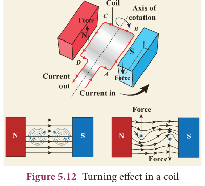
- Now look at the current carrying conductor segment AB.
- The direction of the current is towards B, whereas in the conductor segment CD the direction is opposite.
- As the current is flowing in opposite directions in the segments AB and CD, the direction of the motion of the segments would be in opposite directions according to Fleming’s left hand rule.
- When two ends of the coil experience force in opposite direction, they rotate.
- If the current flow is along the line ABCD, then the coil will rotate in clockwise direction first and then in anticlockwise direction.
- If we want to make the coil rotate in any one direction, say clockwise, then the direction of the current should be along ABCD in the first half of the rotation and along DCBA in the second half of the rotation.
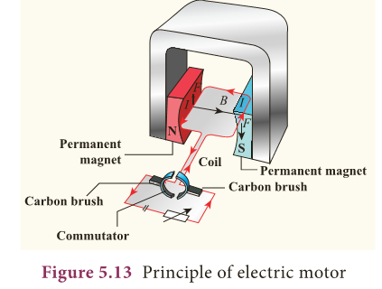
- To change the direction of the current, a small device called split ring commutator is used.
- When the gap in the split ring commutator is aligned with terminals X and Y, there is no flow of current in the coil.
- But, as the coil is moving, it continues to move forward bringing one of the split ring commutator in contact with the carbon brushes X and Y.
- The reversing of the current is repeated at each half rotation, giving rise to a continuous rotation of the coil.
- The speed of rotation of coil can be increased by:
- increasing the strength of current in the coil.
- increasing the number of turns in the coil.
- increasing the area of the coil and
- increasing the strength of the magnetic field.
Electromagnetic Induction
- When it was shown by Oersted that magnetic field is produced around a conductor carrying current, the reverse effect was also attempted.
- In 1831, Michael Faraday explained the possibility of producing an e.m.f across the conductor when the magnetic flux linked with the conductor is changed.
- In order to demonstrate this, Faraday conducted few experiments.
Faraday’s experiments
Experiment 1
- In this experiment, two coils were wound on a soft iron ring (separated from each other).
- The coil on the left is connected to a battery and a switch K.
- A galvanometer is attached to the coil on the right.
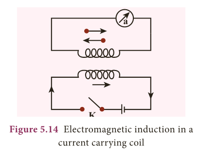
- When the switch is put ‘on’, at that instant, there is a deflection in the galvanometer.
- Likewise, when the switch is put ‘off’, again there is a deflection – but in the opposite direction.
- This proves the generation of current.
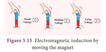
Experiment 2
- In this experiment, current (or voltage) is generated by the movement of the magnet in and out of the coil.
- The greater the number of turns, the higher is the voltage generated.
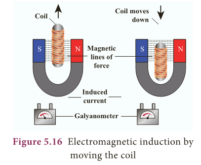
Experiment 3
- In this experiment, the magnet is stationary, but the coil is moved in and out of the magnetic field (indicated by the magnetic lines of force).
- Here also, current is induced.
- All these observations made Faraday to conclude that whenever there is a change in the magnetic flux linked with a closed circuit an emf is produced and the amount of emf induced varies directly as the rate at which the flux changes.
- This emf is known as induced emf and the phenomenon of producing an induced emf due to change in the magnetic flux linked with a closed circuit is known as electromagnetic induction.
- Note: The direction of the induced current was given by Lenz’s law, which states that the induced current in the coil flows in such a direction as to oppose the change that causes it.
- The direction of induced current can also be given by another rule called Fleming’s Right Hand Rule.
Activity 3 (Create your own electromagnet)
- You are given a long iron nail, insulation coated copper wire and a battery.
- Can you make your own electromagnet?
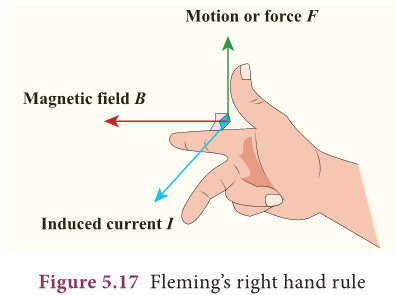
Fleming’s Right Hand Rule
- Stretch the thumb, fore finger and middle finger of your right hand mutually perpendicular to each other.
- If the fore finger indicates the direction of magnetic field and the thumb indicates the direction of motion of the conductor, then the middle finger will indicate the direction of induced current.
- Fleming’s Right hand rule is also called ‘generator rule’.
Electric generator
- An alternating current (AC) generator, as shown in Figure 5.18, consists of a rotating rectangular coil ABCD called armature placed between the two poles of a permanent magnet.
- The two ends of this coil are connected to two slip rings S1 and S2. The inner sides of these rings are insulated.
- Two conducting stationary brushes B1 and B2 are kept separately on the rings S1 and S2 respectively.
- The two rings S1 and S2 are internally attached to an axle.
- The axle may be mechanically rotated from outside to rotate the coil inside the magnetic field.
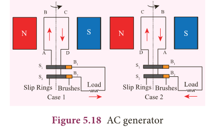
- Outer ends of the two brushes are connected to the external circuit.
- When the coil is rotated, the magnetic flux linked with the coil changes.
- This change in magnetic flux will lead to generation of induced current.
- The direction of the induced current, as given by Fleming’s Right Hand Rule, is along ABCD in the coil and in the outer circuit it flows from B2 to B1.
- During the second half of rotation, the direction of current is along DCBA in the coil and in the outer circuit it flows from B1 to B2.
- As the rotation of the coil continues, the induced current in the external circuit is changing its direction for every half a rotation of the coil.
- To get a direct current (DC), a split ring type commutator must be used.
- With this arrangement, one brush is at all times in contact with the arm moving up in the field while the other is in contact with the arm moving down.
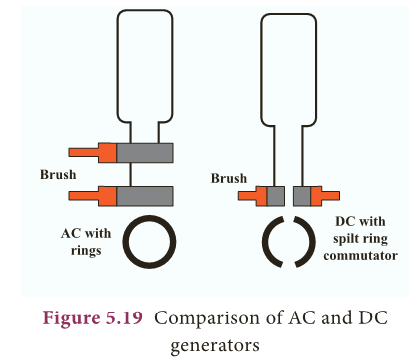
- Thus, a unidirectional current is produced. The generator is thus called a DC generator (Figure 5.19).
Transformer
- Transformer is a device used for converting low voltage into high voltage and high voltage into low voltage.
- It works on the principle of electromagnetic induction.
- It consists of primary and secondary coil insulated from each other.
- The alternating current flowing through the primary coil induces magnetic field in the iron ring.
- The magnetic field of the iron ring induces a varying emf in the secondary coil.
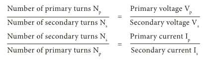
- Depending upon the number of turns in the primary and secondary coils, we can step- up or step-down the voltage in the secondary coil as shown in Figure 5.20.
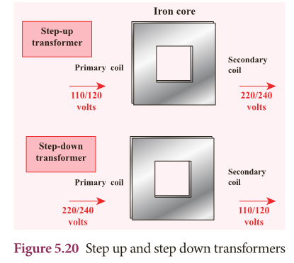
Step up transformer:
- The transformer used to change a low alternativing voltage to a high alternating voltage is called a step up transformer. ie Vs > Vp.
- In a step up transformer, the number of turns in the secondary coil is more than the number of turns in the primary coil (Ns > Np).
Step down transformer:
- The transformer used to change a high alternating voltage to a low alternating voltage is called a step down transformer (Vs < Vp).
- In a step down transformer, the number of turns in the secondary coils are less than the number of turns in the primary coil (Ns < Np).
- The formulae pertaining to the transformers are given in the following equations.
- A transformer cannot be used with the direct current (DC) source because, current in the primary coil is constant (ie. DC).
- Then there will be no change in the number of magnetic field lines linked with the secondary coil and hence no emf will be induced in the secondary coil.
Applications of Electromagnets
- Electromagnetism has created a great revolution in the field of engineering applications.
- In addition, this has caused a great impact on various fields such as medicine, industries, space etc.
Speaker
- Inside the speaker, an electromagnet is placed in front of a permanent magnet.
- The permanent magnet is fixed firmly in position whereas the electromagnet is mobile.
- As pulses of electricity pass through the coil of the electromagnet, the direction of its magnetic field is rapidly changed.
- This means that it is in turn attracted to and repelled from the permanent magnet vibrating back and forth.
- The electromagnet is attached to a cone made of a flexible material such as paper or plastic which amplifies these vibrations, pumping sound waves into the surrounding air towards our ears.
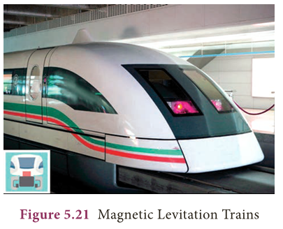
Magnetic Levitation Trains
- Magnetic levitation (Maglev) is a method by which an object is suspended with no support other than magnetic fields.
- In maglev trains two sets of magnets are used, one set to repel and push the train up off the track, then another set to move the floating train ahead at great speed without friction.
- In this technology, there is no moving part.
- The train travels along a guideway of magnets which controls the train’s stability and speed using the basic principles of magnets.
Medical System
- Nowadays electromagnetic fields play a key role in advanced medical equipments such as hyperthermia treatments for cancer, implants and magnetic resonance imaging (MRI).
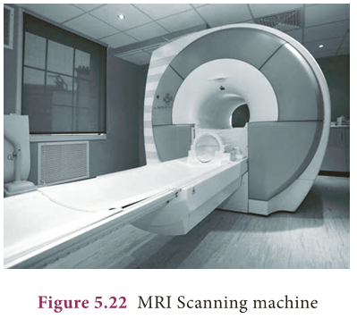
- Sophisticated equipments working based on electromagnetism can scan even minute details of the human body.
- Many of the medical equipments such as scanners, x-ray equipments and other equipments also use the principle of electromagnetism for their functioning.
MORE TO KNOW:
Turtles

- Some sea turtles (loggerhead sea turtle) return to their birth beach many decades after they were born, to nest and lay eggs.
- In a research, it is suggested that the turtles can perceive variations in magnetic parameters of Earth such as magnetic field intensity and remember them.
- This memory is what helps them in returning to their homeland.
Know Your Scientist
- Michael Faraday (22nd Sep,1791–25th Aug, 1867) was a British Scientist who contributed to the study of electromagnetism and electrochemistry.
- His main discoveries include the principles underlying electromagnetic induction, diamagnetism and electrolysis.
A step up transformer
- A step up transformer increases the voltage but it decreases the current and vice versa.
- Basically there will be loss of energy in a transformer in the form of heat, sound etc.
EXTRA POINTS:
- Magnetic field: The region surrounding a magnet in which the force of the magnet can be detected.
- Magnetic line of force: The path followed by a magnetic needle in a magnetic field.
- Dynamo: Device which converts mechanical energy into electrical energy.
- Motor: Device which converts electrical energy into mechanical energy.
- Electromagnetic induction: The phenomenon of producing an induced emf due to change in the magnetic lines of forces associated with a conductor.
- Transformer: Device which converts low alternating current to high alternating current and vice versa.
- MRI: Devise used to obtain images of the internal parts of our body.